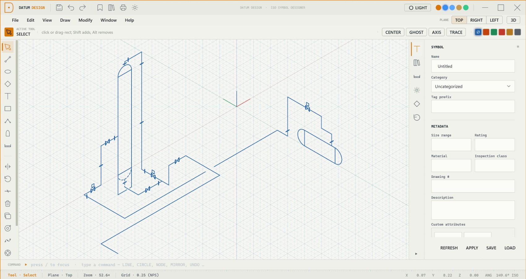
Datum · Symbol Designer

Draw the isometric symbols your drawings are built from.

A Windows CAD studio for authoring isometric piping and pressure-vessel symbols — draft across three iso planes, place typed connection nodes, and save reusable, metadata-rich symbols for your ISO drawings.

Windows desktop · .NET 10 · isometric CAD · Blueprint & Pro CAD themes

Datum Design — isometric symbol editor with a pressure vessel and piping drawn across iso planes

What it is

The symbols behind every isometric.

Datum Design draws engineering symbols, not free-form art — isometric geometry annotated with the connection points and metadata your ISO drawing tools consume.

Three iso planes

Every element is drawn on Top, Right or Left — projecting correctly and unprojecting cleanly to 3D.

Typed connection nodes

Color-coded pipe ports carry direction, type and size — so designers snap pipe runs straight onto your symbol.

Metadata-rich

Category, tag prefix, rating, material, drawing # and inspection class travel with every symbol.

The drafting engine

Precision isometric drafting.

A retained-mode canvas renders the scene in layers — grid, geometry, guides and live tool preview — so it redraws only what changed and stays crisp at any zoom. Draw on an iso, square or engineering grid and orbit the view into 3D at any time.

  • Three iso planes — Top (XY), Right (XZ) and Left (YZ)
  • Iso, Square & Engineering grids with configurable spacing
  • Zoom, pan and free-orbit with the cursor point held fixed
Datum Design — isometric grid canvas with the three-axis origin and drafting tools

Precision aids

Snap, track and mirror like a pro CAD tool.

A multi-pass snap engine, accelerated by spatial hashing, keeps dense symbols snapping interactively — the AutoCAD muscle memory carries straight over.

10 object snaps

Grid, endpoint, midpoint, center, node, origin, on-arc, tangent and perpendicular.

Polar tracking

OTRACK-style rays along 0° / 30° / 90° / 150°, snapping to ray intersections.

Smart guides

Glowing alignment guides when the cursor lines up with an iso axis through an anchor.

Smart-Trace

Routes a two-click line as an iso-aligned path with at most one elbow.

Ghost Symmetry

A live mirror preview of new geometry across a saved symmetry axis.

Keyboard-first

Single-key tools and an AutoCAD-style typed command bar with aliases.

The tool set

Every tool a symbol needs — undoable to the last edit.

Tools never touch geometry directly; each gesture emits an undoable command, so Undo / Redo restores every drawing exactly.

Draw

Line & Polyline

iso segments / chains

Iso Circle / Arc

true 3D → iso ellipse

Rectangle

on the active plane

Text & Dimension

iso-snapped labels
Modify

Select & Move

box / shift-click

Rotate & Mirror

iso-aware

Fillet / Chamfer

corner edits

Offset & Break

geometry edits
Generate

Head Maker

parametric vessel heads

Flange

bolt-pattern generator

Linear Array

count + spacing

Circular Array

radial copies
Parametric geometry

Heads, flanges and typed ports.

Cap a pressure vessel with a parametric head, generate a bolt-pattern flange in one gesture, and place pipe connection nodes that carry their type, direction and size — color-coded so a piping designer can snap runs together at a glance.

  • Vessel heads — hemispherical, 2:1 ellipsoidal or F&D, with seam modes
  • Bolt-pattern flange — three rings and N bolt nodes, generated
  • Required & snap-only ports with auto-tagging prefixes (PSV, HV, V…)
Process Drain Vent Instrument Utility Inspection
Datum Design — a vessel with heads and flanges drawn isometrically with connection nodes

Symbols & library

Author once, reuse everywhere.

Save a symbol to the native .dtm format or drop sub-components into a shared library — standard valves and fittings are seeded on first run.

Reusable symbols

Each drawing is a single Symbol definition in symbol-local coordinates — saved as a portable .dtm file.

Component library

Transplant a valve, vessel or assembly into a host symbol at an anchor point — seeded with standards.

11 symbol categories

Pressure vessels, valves, fittings, instruments, rotating equipment, line components and more.

Optional 3D engine

Promote the iso into 3D.

A self-contained real-time engine lifts the 2D isometric symbol into a navigable 3D mesh. Orbit it, walk through it, or explode it — the viewport is off by default and toggled on demand.

  • 2D → 3D promotion turns iso geometry into mesh on demand
  • Orbit & walk cameras, preset views and smooth transitions
  • LOD, culling, exploded view and mesh streaming for big assemblies
Datum Design — isometric valve and flange symbols visualized with dimensions

Look & feel

Two professional themes, your accent.

A clean, engineered aesthetic — sharp corners, restrained accents — with five preset accent colors you can switch live.

Blueprint

Light · drafting on vellum paper · industrial amber accent

Pro CAD

Dark · modern graphite workstation · engineering blue accent

Output & formats

From symbol to sheet.

Native .dtm format

A JSON envelope wrapping a single symbol definition — portable, and legacy bare-JSON files still open.

PDF template backgrounds

Drop a sheet behind the grid — bundled 8.5×11 and 11×17 ISO sheets, plus an NDT / UTS inspection template.

Print & export

A dedicated print-layout system with paper and viewport management, plus image export via the render pipeline.

See it draw

Build a symbol on the call.

We’ll draft a vessel or valve isometrically, place its connection nodes, and save it to the library — so you can see exactly how Datum Design fits your drawing workflow.

support@sifulogic.com